I’ve recently been going back to the 3D printed models my students designed in my Math 341 Introduction to Topology class in Fall 2014. I know so much more now than I did then when I first started on this journey. So, I decided to go back to the designs, check over them, edit them (as necessary), then reprint them and publish them on Thingiverse.
The first two models I looked at where Candace Bethea’s (’15) \(6_2\) knot and Hayley Archer-McClelland’s (’15) three interlocking trefoils. In a previous class using 3D printing, Professor Aaron Abrams contacted the developer of the program Seifert View, and arranged for the computed curves and surfaces to be able to be exported as a file. (This free software normally doesn’t allow you to do this.) We have since found this to be an invaluable tool for 3D printing knots and knots with Seifert surfaces.
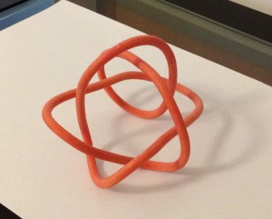
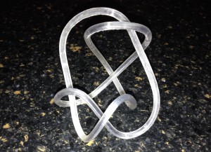
The \(6_2\) knot was first adjusted in, then exported from SeifertView, and then opened in Cinema4D. The surface of the knot needed fixing due to overlapping polygons. This was fixed by deleting overlapping polygons, then filling in the gaps using the Stitch and Sew tool in Edge mode. The knot was originally printed in orange on the Projet-260 3D Systems printer. Later, I printed it on the FormLabs 1+ printer in clear resin. You can find the model here on Thingiverse.
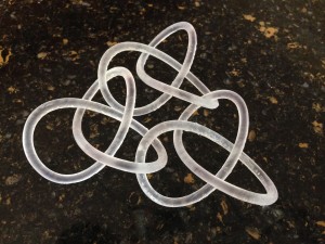

The three interlocking trefoils were designed entirely in Cinema4D. The parametric equations of a trefoil knot are \(x(t)= (2+\cos(3t))\cos(2t), y=(2+\cos(3t))\sin(2t), z=-\sin(3t)\) for \(t\in[-\pi, \pi]\). We first made the curve with the Formula tool for \( t\in[-3.14, 3.14]\). We added a SweepNurb (with no caps) consisting of a circle with radius 0.2 cm around the curve. The choice of \(t\) meant there was a small gap between the ends of the tube. We again sealed this gap using the Stitch and Sew tool in Edge mode. The knots were originally printed in pink, pale green and blue on the Projet-260 3D Systems printer. Later, I printed it on the FormLabs 1+ printer in clear resin. You can find the model here on Thingiverse.

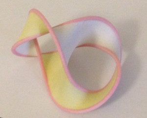
Mithra Muthukrishnan (’16) used Seifert View to design a figure-8 knot and its Seifert surface. After tweaking in Seifert View, she exported the surface to Cinema4D. It ended up being a complex design process, since we wanted to color the knot and two sides of the surface with different colors. There, the surface was extruded in both directions creating the two sides of the Seifert surface. Finally, three copies of the surface were made. In one, all the surfaces were deleted leaving the knot. In another the knot and one side of the extrusion was deleted. In the final copy, the knot and the other side of the extrusion was deleted. This left three pieces which could each be given their own color before printing. The knot was colored red/pink, the different sides of the Seifert surface were colored white and yellow. The model was originally printed in color on the Projet-260 3D Systems printer. Later, I printed it on the MakerBot 2x printer in bright white. You can find the model here on Thingiverse.

The octopus model was designed by DanJoesph Quijada (’15) entirely in Cinema4D. The legs were made using parametric equations like \(x(t) = a\sqrt{2}t, y(t)=0, z(t) = b^2 cos^2(ct)e^{-dt^2}\) for various constants \(a, b, c,\) and \(d\), and bounded time \(t\). These curves were then thickened using a SweepNurbs. To make the octopus head, we first made a box, then extruded parts of the sides to alter the shape, then applied the Subdivision Surface tool to it. Finally we made minor adjustments, such as adding the eyes and changing the dimensions of the octopus to make it look more realistic. The model was originally printed in pink on the Projet-260 3D Systems printer. Later, I printed it on the MakerBot 2x printer in bright white, though I had some trouble with the legs. You can find the model here on Thingiverse.
 In early May, the IQ center at W&L was filled with 3D-printed flowers. Dave Pfaff and his work study students printed flowers in many bright colors on the Cura 3D printer. They are from Super Flowers found on Thingiverse. The fine filaments are created by printing in the air. That’s right, the printer puts down a single layer of material, then returns to the center. Since there are no supports underneath, a “droop-loop” of filament is created.
 The vases were also designed by Dave Pfaff. He started with a flower shape on the base, then expanded and twisted the shape around creating the vase shape we see. Fabulous work!


