Intersecting Cylinders – The Steinmetz Solid

My next goal was to print two cylinders whose axes intersect at right angles and the volume common to both, otherwise known as the Steinmetz solid. I began by modeling these objects in Mathematica so I could import the objects to Cinema 4D as well as create an interactive Mathematica worksheet about these objects.

Here are the Mathematica representations of two objects I planned to print:Screen Shot 2015-06-30 at 3.30.42 PM Screen Shot 2015-06-26 at 1.30.03 PM
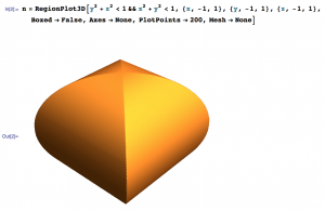
I exported the top object as a .wrl file into Cinema 4D since it was already a solid.

For the bottom object,  I decided it would easiest to create it from scratch in Cinema 4D using the “Tube” object and simply adjusting the dimensions and orientation.

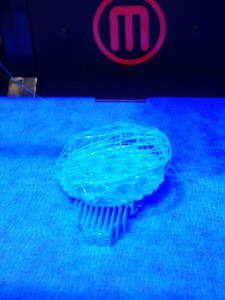
I attempted to print the intersecting cylinders on the Afinia printer in the Math Department. It failed to finish printing because the filament got tangled coming off of the spool. However this was not a complete fail since it shows the inside of the two cylinders and can still be used as a teaching tool. 

I am currently attempting to reprint it and will see how it goes! 

Update: The filament got tangled once again while I was printing resulting in a similar object to the one above. We decided that these were both better teaching tools than the original design and decided not to try to print again. 

I printed the Steinmetz solid on the MakerBot 2x and had great results! This object can be found on Thingiverse here and here.


Walking down memory lane

In Fall of 2014 I taught Math 341 Introduction to Topology. As part of the class I had the students design and then print a topological object. For most students, this ended up being the highlight of the course.

10482770_4584418265143_4975820982335381144_n-1We spent a week of class in the IQ center under the guidance of David Pfaff. He showed us how objects can be viewed in the stereo 3D lab and gave us a crash course in Cinema 4D. Students then let loose their imaginations and creativity. Many students chose to learn about knots and links, ribbon knots, and Seifert surfaces of knots and links. They produced some wonderful models. Other students chose to create objects with symmetry (like the 20 sided die), or the cube-like Cayley graph.

It turned out that getting the objects that could be 3d printed was hard work! Many objects had not been optimally made (for example with normal vectors pointing inwards). We were fortunate to have David Pfaff’s expertise in sorting out these errors. Eventually all the objects were printed using the IQ center’s ProJet 260. Some of them needed to be printed twice, as they broke when being removed from the printer. Many 3d printed math objects from this class and from Aaron Abrams first year seminar currently reside in the Mathematics Department.


Solid of Revolution – Comparing Methods #1

We decided to find a solid of revolution for which both the washer method and cylindrical shell method worked and to model it with both methods. Laura Taalman has done similar designs for shell approximations which can be found here and here

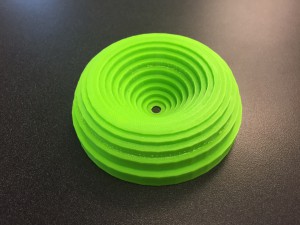
We decided to rotated the area between \(y=x\) and \(y=x^2\) about the line \(y=1.25\). This created a bowl-like object which is curved on the outside, straight on the inside and with a hole at the bottom of the bowl. We split this project up and I created a model of the object using the washer method, while Ryan used the cylindrical shell method. We planned to each use 16 slices/shells so we could compare our two models later.

Creating this object was a very similar process to that of creating the sphere with washers. Since I was using 16 washers and the object has a height of 1, each washer was 1/16 thick. In Cinema4D I used the preprogramed tube object and made each of them to have a height of 1/16. In order to calculate the inner and outer radius of each washer I used the value of middle of each washer, 1/32, 3/32, 5/32, 7/32, etc. I plugged these values into the equation \(f(x)=1.25-x\) for the inner radius value and \(g(x)=1.24-x^2\) for the outer radius value. The only other thing I had to change for each was was its height coordinate. My washers in Cinema4D were parallel to the \(xz\)-plane so I adjusted each washer’s \(y\)-coordinate so they would be spread out to the correct height. I increased the \(y\)-coordinate of each was by 1/16 (the height of each washer) from the previous. 

Since I used the preprogramed tube object I was unable to use Magic Merge easily to connect these object and instead just used the ‘Connect + Delete’ command under the ‘Mesh’ tab. This means that there are inner walls in my object, but since each washer is relatively small this is not hugely problematic and adds extra support.

I ran into one issue when I was finishing up with my object. The smallest washer (and the last one I created) did not touch the previous washer. Screen Shot 2015-06-23 at 3.09.54 PMAll the other washers had been able to lie on top of the previous one since their outer radius was larger than the inner radius of the previous washer. The 15th washer had an inner radius of 0.34375 cm and the 16th washer had an outer radius of 0.31152cm and thus there was a gap. This is due to the fact the bowl is very flat at the bottom.

We decided to remedy this we would just delete the 16th washer and make a note of it here as well as in the description of the object on Thingiverse.

We printed Ryan’s object with cylindrical shells using the Makerbot and the supports on the inside were difficult to remove and didn’t look good. We are currently discussing printing on another printer for these objects and I will update later on how that goes!

Volumes by Slicing – General Slices

My second project this summer was to create a solid with a circular base and with equilateral triangles as the parallel cross-sections perpendicular to the base. I modeled this solid with 20 triangles and 10 triangles.

In order to create the triangular prism cross-sections I used Mathematica. I decided to use the circle \(x^2+y^2=25\) for my base, and assumed that the cross-sections were perpendicular to the \(y\)-axis. In Mathematica, the triangular prisms were created using coordinates for the three vertices and the desired thickness. For the 20-slice object each triangle prism was 0.5 cm thick and for the 10-slice object they were 1 cm. I calculated the three coordinates for each cross-section by using the midpoint of each slice. So for the 20-slice object I used \(y\)-values of 0.25, 0.75, 1.25, 1.75, 2.25, 2.75, 3.25, 4.25, and 4.75. (I only had to use 10 values since due to the symmetry of the circle.) Similarly, for the 10-slice object I used \(y\)-values of 0.5, 1.5, 2.5, 3.5 and 4.5. I then calculated the \(x\)-formula for the points on the circle using \(x=\sqrt{25-y^2}\). The three coordinates of the triangle were then \((-x,y), (x,y) \), and \((0,x\sqrt{3})\). To make it easier to create the triangular prisms in Mathematica, I shifted the bottom left corner to each triangle to the origin so that the three coordinates for my equilateral triangles were \((0,0), (2x, 0) \), and \( (x, x\sqrt{3}) \). After creating each slice I exported the triangular prisms from Mathematica as .wrl files and imported them into Cinema 4D.

In Cinema 4D I arranged each slice to have the correct coordinates and created my objects. Since these slices were created in Mathematica I could extend them from only one side and not both (like with the disks in my previous post). This was perfect for using the plugin Magic Merge. I wanted to extend the triangles from one side into the larger one next to them in order to use Magic Merge. This is where I ran into trouble! Each triangle would only extend from one side and, since the smaller triangles had to overlap with larger ones in order to maintain the mathematical accuracy from my calculations, that meant half of them wouldn’t overlap.

In order to fix this, I had to rotate those individual triangles 180° and changed their coordinates accordingly so that I would be able to extend them correctly to overlap. Once I had done this I used Magic Merge to create the solid and then exported the .stl file for printing.

IMG_4524When I went to print my object upright I ran into some problems. It seemed that I had forgotten to merge part of the object and it was printing the inner walls upright which resulted in double the print time and cost. I rotated the object so that the slices were parallel to the build bed – this meant the print required supports. It now looked correct in print preview and printed correctly. My final object from this print looked good, but was rough on one side from removing the supports and I knew if I could fix my problems I would be able to print it with a hollow inside and without supports.

I went back and merged all of my cross sections again (and this is another reason to always save a separate file of your object before you merge because this makes things a lot easier to check). Now when I exported the file and went to print, my print preview only had certain parts of the object showing up. When I tried to fix this I realized that I hadn’t checked the normals of the slices I had imported from Mathematica. Going back to my saved file I changed the normals so they all aligned in the correct direction. Now I could finally print my object upright with a hollow inside thanks to Magic Merge. These objects can be found on Thingiverse here and here.

IMG_4521

An unexpected bonus

Quadratic_Surfaces We have made some wonderful 3d printed models recently. As an unexpected bonus we have also created some great Mathematica notebooks. These were developed as we first created the shapes in Mathematica, then imported them into Cinema 4D, to finally create the .stl file ready for 3d printing. The notebooks have a mix views of the shapes and also some neat Mathematica Demonstrations that can be used when teaching. They can be found here.

Volumes_TripleIntegrals     Two_intersecting_cylinders


Exercise 32

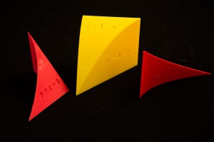
Next, I made a model of the volume from Exercise 32 in Section 12.5 of Stewart’s Essential Calculus. This solid is the region of integration enclosed by the surfaces \(x=0, y=0, y=1-x\), and \(z=1-x^2\).

32_3      32_2

This model is my best by far because the edges are almost perfectly smooth, and each face is very flat. It took about three hours to print, and the only deformities are a little bubble near one edge and the red outline around “\(z=0\)” from of the residual red filament in the extruder. I exported the piece from Mathematica into Cinema 4D, then imprinted the equations into their respective faces (see http://home.wlu.edu/~dennee/math_vis.html for further detail). For this solid I used 300 PlotPoints instead of 100 (see Mathematica code below) and it paid off in the smooth definition of the curved edge, which is almost perfect.

32_1

You can find this object on Thingiverse here.

DSC_1140       DSC_1136

Wedge 2

                                   new_wedge_1

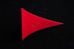
We made some changes before re-printing the wedge enclosed by the surfaces \(x=0, z=0, z=1-y\), and \(x=y^2\). I altered the PlotPoints in the Mathematica code from 100 to 400, which made the curve of intersection between the \(x=y^2\) and \(y+z=1\) surfaces smoother on Cinema 4D.  I also made each side about 8 cm long instead of 7 cm and I made the equations larger.

The result was that the top vertex still looks messy and the  “\(z\)” on the bottom face of the object is not clear, but that can be fixed with a razorblade (see image below). Changing the PlotPoints in the Mathematica code made the curve much smoother and the equations look nicer. You can find this object on Thingiverse here.

new_wedge_4              new_wedge_3           


Wedge 1

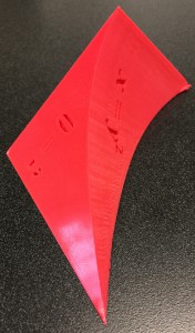
DSC_1148 Next, I made a model of the volume from Exercise 31 in Section 12.5 of Stewart’s Essential Calculus, which is a wedge with a parabolic cylinder cut out of it.  The wedge is enclosed by the surfaces \(x=0, z=0, z=1-y\), and \(x=y^2\). First I made the solid in Mathematica from the following code (from Professor Keller and Professor Denne):

mathematica_code_1Then I exported it into Cinema 4D by typing the following:

export_code_mathematica


Then I opened the resultant .wrl file in Cinema 4D. The \(x=0\) is tangential to the curved face, so it would not print unless you cut about a half centimeter off of the tangential surface near the \(z\)-axis (I used a Boolean with the solid and a cube to do this). Additionally, I made equations in Adobe Illustrator (I used Times New Roman 36 Bold Italic font). I then extruded them in Cinema 4D to create 3-dimensional letters, and then imprinted them into the four faces of the object. For further instructions, visit http://home.wlu.edu/~dennee/math_vis.html.

The model looked reasonably good after being printed. The bottom face came out nicely. Near the \(z\)-axis, the solid curled up. Also, the upper edge of the \(x=y^2\) face was a bit jagged, but that can be fixed by changing the Mathematica code (increasing the number of PlotPoints). Additionally, the top vertex of the solid is quite messy, which could be fixed by printing the figure on the slanted face (\(y+z=1\)). Also, Professor Finch suggested that the object could be made a bit larger. A description of improvements to the design and what happened in the second print follows soon. You can find the updated solid on Thingiverse here.

DSC_1136

Volume by Cylindrical Shells

shells_1On Monday, June 15, I modeled a volume by cylindrical shells from Calculus II.  I used Example 1 in 7.3 of Stewart’s Essential Calculus, which is a volume of revolution of the curve \(y=2x^2-x^3\) about the y-axis. This is shaped a bit like a stadium. The plan is to approximate this volume using 16 cylindrical shells. I first sketched out the curve in 2-dimensions to get a feel for the profile of the shape. Next, I wrote out each point on the curve from \(x=0\) to \(x=2\) in intervals of length 1/8, namely \((0,0), … , (1.875,0.439), (2,0)\).

Each cylindrical shell is determined by its height, the thickness of the shell and either the inner or outer radius. By construction, each shell has thickness 1/8 and for each \(k=0,1,2, \dots, 15\), the inner radius of a shell is \(k/8\), while the outer radius is \((k+1)/8\). I chose the height of each shell to be \(f(k/8)\), which is the the \(x\)-value closer to the origin.

To summarize, if \(r=\)inner radius of shell, \(R=\)outer radius of shell, and \(h=\)height of tube, then for \(k = 0, 1, 2, \dots , 15\),

$$r = k/8,  \quad R = (k+1)/8,  \quad h=2r^2 – r^3.$$

Since the height function is increasing between \(x=0\) and \(x=4/3\), the cylindrical shells lie inside the volume of revolution. Between \(x=4/3\) and \(x=2\), the function is decreasing and the shells lie outside the volume.

shells_2I then made a model of this Riemann approximation for the solid in Cinema 4D by inserting tubes (Cinema 4D’s name for “cylindrical shells”) of inner radius \(r\), outer radius \(R\), and height \(h\). When Cinema 4D inserts a tube, it places half of the tube above the \(xy\)-plane (the \(xz\)-plane in Cinema 4D) and half of it below. Therefore, I needed to add half of each tube’s height to put each shell onto the \(xy\)-plane.

The object was first printed with the supports setting on just in case, although I thought that they did not need supports. The result was that a couple superfluous strands of plastic running along the shells, which needed to be removed. Given the geometry of the shape, I would advise against using supports in building this object.

I would advise that you use a raft to build this object, however, because it was very difficult to remove the object from the build plate. (It took 5 minutes of very careful tugging by David Pfaff.)

You can find this objects on Thingiverse here.

My First Printing Failure

IMG_4460When I printed my sphere with 20 disks I oriented the object so the disks were parallel to the build bed, as I had done with the 10-disk sphere. However, when I removed the sphere from the build bed, the bottom disk popped off and remained stuck to the build bed. This was the first failure I had while printing.

In order to remedy this problem I decided to try printing the sphere with the disks perpendicular to the build bed. I hoped this would fix our problem when it came to removing the object.

We had just finished unpacking and setting up the Mathematic Department’s MakerBot Replicator 2 after it had been in storage for awhile so we and decided to test it with the rotated sphere. This proved to be problematic for many reasons.

IMG_2505First, the nozzle of the printer became clogged, resulting in a mess of plastic as shown below. We didn’t know what the problem was at this point so we tried twice more only to result in the same mess of plastic filament.IMG_2506

Once we figured out that was the problem and our printer needed fixing, I decided to try again on the MakerBot 2X in the IQ center. When I set up the file to print and looked at the print preview I saw it was using twice as much material and would take twice the amount of time to build this sphere even though it was the same size as the old one. Clearly my design had issues.

Looking back at my Cinema 4D file I realized that the object had walls inside of it between each disk and was not completely hollow. This meant when I printed the object with disks perpendicular to the build bed it needed much more support, and thus the extra time and material to build it. At this point I realized I needed to change the design and create a hollow object.

In order to do this the IQ center’s David Pfaff suggested I try a plugin for Cinema 4D called Magic Merge. The instructions for downloading and using Magic Merge can be found here.

Unfortunately there are some limitations to Magic Merge as I quickly found out with my object. Objects must overlap slightly in order for Magic Merge to work. Since I had created and placed my disks to be mathematically accurate, this proved to be a problem. When I tried to expand the disks into each other they expanded in both directions, making the object inaccurate. To use Magic Merge and keep my object accurate would have been very complicated and time consuming so I decided not to. However with other objects Magic Merge can be very useful.

Instead, I reprinted the original object with disks parallel to the build bed and was very careful in removing it so the bottom disk did not pop off again.