Quadratic Surfaces – Hyperboloid of One Sheet

My first successful print of a quadratic surface was a hyperboloid of one sheet.

Screen Shot 2015-07-15 at 2.16.58 PM

I began this project by creating a solid hyperboloid of one sheete in Mathematica. I didn’t like this object since it was a complete solid and not the surface I was trying to create.


To make the surface I originally attempted to import a Mathematica file of the surface into Cinema 4D and then give it thickness. This quickly became a nightmare to deal with. I had to be extremely careful about how many plot points I used in Mathematica because too many created too many polygons. These polygons also overlapped and so when I tried to extrude them to give the surface thickness the normals were off and it resulted in a very jagged surface. After spending hours trying to work with my Mathematica file I decided to try to create the surface from scratch in Cinema 4D.

In order to do this I used a ‘formula spline’. In Cinema 4D ‘formula splines’ are created using parametric equations. I used the equations \(x(t)=sinh(t), y(t)=cosh(t), z(t)=0\). I then rotated this spline 360 degrees using the Lathe tool. I then optimized the polygons in order to fully connect the object where the spline’s rotation began and end. Once this was done I was able to extrude the polygons to give the surface thickness using the polygon extrude and being sure to add caps to my extrusion.

Screen Shot 2015-07-15 at 2.29.00 PMOne this was done I had my object complete. The next step was to add equations. Using the instructions for how to put equations on solids I created my equations. In order to put them on the solid I used the bend tool in Cinema 4D. Using this tool was very difficult and took a lot of playing with to make it look good. The first thing I had to do was fit the bend box and rotate it in order to bend my equation correctly. When I went to bend the formula to fit my object, I found I needed to align only the first part of the equation on the left hand side with the surface (and not the center of the formula) since the bend tool bent the equation from the left and not at the center.

The first time I printed my object I realized the equations I had put on my object were far too small. I went back to my Cinema 4D file and make them bigger to get my final object! This object can be found on Thingiverse here.

hyperboloid1sheet-2hyperboloid1sheet-1


Tetrahedra

IMG_1117                                 IMG_1120


I made two tetrahedra, both of which demonstrate the strategy behind setting up triple integrals. One tetrahedron came from our calculus textbook, another came from Professor Keller. The former is defined by the equations \(x + 2y + z – 2, x = 2y, z = 0\), and \(x = 0\) (ExaIMG_1121
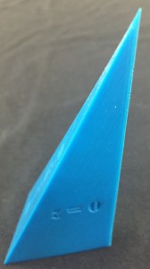
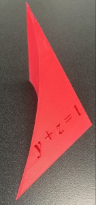
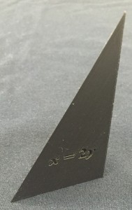
mple 5 of 12.5 in Stewart’s Essential Calculus), and the latter by \(y=-6, z=0, z=x+4\), and \(2x+y+z=4\). When I first tried to print the Tetrahedron from the textbook, the equation on the bottom face did not appear. Later, Dave Pfaff told us that it was because the object was inside out in Cinema 4D. I fixed the issue by reversing the normals on the object.

I then tried to print the object in addition to a set of round coordinate axes, but one of the axes was either knocked out of position by the left extruder (the unused one) or it curled up because it cooled (or maybe both). Later, I tried to print the tetrahedron with Prof Keller’s tetrahedron, but they curled up at the ends because the cooling of the plastic is exacerbated when the length IMG_1115
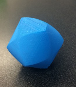
increases. Next, I used a raft to print the two shapes, but the equations looked awful. So then I used some ABS juice on the half of the build-plate that contained the sharp vertex of Professor Keller’s tetrahedron and the print came out well, except for a messy-looking number “4” and some stringy filament on one of the faces (see blue shape).

Finally, I printed Professor Denne’s tetrahedron along with another set of coordinate axes (see black objects). Since there was some juice left over on the build-plate, the only end that curled up was at the origin of the coordinate axes, and the rest of the objects looked great.  These tetrahedra can be found on Thingiverse here and here.

IMG_1123

Coordinate Axes

axes_2     axes-black4

I made a set of Coordinate Axes to go along with my two wedge solids from Multivariable Calculus.  The axes will also work well for my Double Riemann Approximations, my tetrahedra (coming soon), and other objects that I will print in the future.  The first issue with the axes was figuring out how to connect each part  – I tried using six rectangular prisms and Magic-Merge to join them together, but that did not work.  Later, with the help of Dave Pfaff, I extruded the coordinate axes out of a cube at the origin.  I then was able to imprint the labels for each of the axes much more easily. The axes can be found on Thingiverse here.

Approximating a Volume by Rectangular Prisms

French-Fries

Next, I modeled the volume under the curve \(z = 16 – x^2 – 2y^2\), using a double Riemann sum approximation. Here, in the \(xy\)-plane, each approximation contains \(m\) squares along the \(x\)-axis and \(n\) squares along the \(y\)-axisScreen Shot 2015-07-01 at 10.02.27 AMIn this case, I used \(m = n = 4\) and \(m = n = 8\).  In order to print the solids, I modeled them on Cinema 4D.  They were extremely thin (the height was much greater than the width and length) (see Cinema 4D pictures), so I divided the height of each approximation by 4.  I then printed them simultaneously, which took 8 hours and 45 minutes.  


The models turned out well, except in the \(m = n = 8\) case the printer did not print one of the rectangular prisms because I accidentally placed two rectangular prisms in the same place.   I then printed a c
orrected version as well as a model of the original solid (height divided by 4 once again).  On the original solid, I imprinted the equation onto the bottom, which does not look great because it should be imprinted deeper into the solid.  We considered using Magic Merge because the first print of the \(m = n = 8\) approximation printed some vertical lines, but when we fixed the model in Cinema 4D, the MakerBot printed smooth faces on each side.

The three objects can be found on Thingiverse  here, here, and here.

Three Intersecting Cylinders

Screen Shot 2015-07-10 at 10.36.08 AMMy latest project was to create three intersecting cylinders and the area of their intersection. I created these objects similarly to the two intersecting cylinders and the Steinmetz solid. For the volume common to all three cylinders I used a Mathematica code and imported the object into Cinema 4D.

Screen Shot 2015-07-10 at 10.43.19 AM
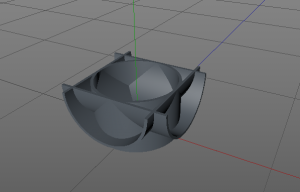
For the three cylinders I created them from scratch in Cinema 4D using the ‘Tube’ object. Creating the three cylinders was very straightforward. After my fail from the two cylinder object I also wanted to create the three intersecting cylinders cut in half, so the inside was visible. This proved to be a little more complicated. I used a ‘Cube’ and ‘Boole’ with each tube in order to get half cylinders. Then I was able to merge them together using a very similar process to putting equations on solids in Cinema 4D.

IMG_4560

I have yet to print the half cylinder object, but I did print the inside intersection. The first time I printed it I ran into a problem that also occurred with the Steinmetz object. Both solids seemed to have ‘melty’ sides. The angle of the object was such that no supports were needed and yet gravity seemed to affect the plastic and cause some issues. We think that the plastic filament cooled and shrunk during printing causing the deformations.

IMG_4562 IMG_4563

In order to fix this I decided to reprint the inside intersection with a different orientation. this required more supports but we had much less melting on the sides. I plan to try reprinting the Steinmetz object with another orientation to see if I can eliminate the deformed sides.

The original orientation is on the left and the new orientation is on the right. The objects can be found on Thingiverse here and here.

IMG_4564IMG_4565


Intersecting Cylinders – The Steinmetz Solid

My next goal was to print two cylinders whose axes intersect at right angles and the volume common to both, otherwise known as the Steinmetz solid. I began by modeling these objects in Mathematica so I could import the objects to Cinema 4D as well as create an interactive Mathematica worksheet about these objects.

Here are the Mathematica representations of two objects I planned to print:Screen Shot 2015-06-30 at 3.30.42 PM Screen Shot 2015-06-26 at 1.30.03 PM

I exported the top object as a .wrl file into Cinema 4D since it was already a solid.

For the bottom object,  I decided it would easiest to create it from scratch in Cinema 4D using the “Tube” object and simply adjusting the dimensions and orientation.

I attempted to print the intersecting cylinders on the Afinia printer in the Math Department. It failed to finish printing because the filament got tangled coming off of the spool. However this was not a complete fail since it shows the inside of the two cylinders and can still be used as a teaching tool. 

I am currently attempting to reprint it and will see how it goes! 

Update: The filament got tangled once again while I was printing resulting in a similar object to the one above. We decided that these were both better teaching tools than the original design and decided not to try to print again. 

I printed the Steinmetz solid on the MakerBot 2x and had great results! This object can be found on Thingiverse here and here.


An unexpected bonus

Quadratic_Surfaces We have made some wonderful 3d printed models recently. As an unexpected bonus we have also created some great Mathematica notebooks. These were developed as we first created the shapes in Mathematica, then imported them into Cinema 4D, to finally create the .stl file ready for 3d printing. The notebooks have a mix views of the shapes and also some neat Mathematica Demonstrations that can be used when teaching. They can be found here.

Volumes_TripleIntegrals     Two_intersecting_cylinders


Exercise 32

Next, I made a model of the volume from Exercise 32 in Section 12.5 of Stewart’s Essential Calculus. This solid is the region of integration enclosed by the surfaces \(x=0, y=0, y=1-x\), and \(z=1-x^2\).

32_3      32_2

This model is my best by far because the edges are almost perfectly smooth, and each face is very flat. It took about three hours to print, and the only deformities are a little bubble near one edge and the red outline around “\(z=0\)” from of the residual red filament in the extruder. I exported the piece from Mathematica into Cinema 4D, then imprinted the equations into their respective faces (see http://home.wlu.edu/~dennee/math_vis.html for further detail). For this solid I used 300 PlotPoints instead of 100 (see Mathematica code below) and it paid off in the smooth definition of the curved edge, which is almost perfect.

32_1

You can find this object on Thingiverse here.

DSC_1140       DSC_1136

Wedge 2

                                   new_wedge_1

We made some changes before re-printing the wedge enclosed by the surfaces \(x=0, z=0, z=1-y\), and \(x=y^2\). I altered the PlotPoints in the Mathematica code from 100 to 400, which made the curve of intersection between the \(x=y^2\) and \(y+z=1\) surfaces smoother on Cinema 4D.  I also made each side about 8 cm long instead of 7 cm and I made the equations larger.

The result was that the top vertex still looks messy and the  “\(z\)” on the bottom face of the object is not clear, but that can be fixed with a razorblade (see image below). Changing the PlotPoints in the Mathematica code made the curve much smoother and the equations look nicer. You can find this object on Thingiverse here.

new_wedge_4              new_wedge_3           


Wedge 1

DSC_1148 Next, I made a model of the volume from Exercise 31 in Section 12.5 of Stewart’s Essential Calculus, which is a wedge with a parabolic cylinder cut out of it.  The wedge is enclosed by the surfaces \(x=0, z=0, z=1-y\), and \(x=y^2\). First I made the solid in Mathematica from the following code (from Professor Keller and Professor Denne):

mathematica_code_1Then I exported it into Cinema 4D by typing the following:

export_code_mathematica


Then I opened the resultant .wrl file in Cinema 4D. The \(x=0\) is tangential to the curved face, so it would not print unless you cut about a half centimeter off of the tangential surface near the \(z\)-axis (I used a Boolean with the solid and a cube to do this). Additionally, I made equations in Adobe Illustrator (I used Times New Roman 36 Bold Italic font). I then extruded them in Cinema 4D to create 3-dimensional letters, and then imprinted them into the four faces of the object. For further instructions, visit http://home.wlu.edu/~dennee/math_vis.html.

The model looked reasonably good after being printed. The bottom face came out nicely. Near the \(z\)-axis, the solid curled up. Also, the upper edge of the \(x=y^2\) face was a bit jagged, but that can be fixed by changing the Mathematica code (increasing the number of PlotPoints). Additionally, the top vertex of the solid is quite messy, which could be fixed by printing the figure on the slanted face (\(y+z=1\)). Also, Professor Finch suggested that the object could be made a bit larger. A description of improvements to the design and what happened in the second print follows soon. You can find the updated solid on Thingiverse here.

DSC_1136