
We decided to find a solid of revolution for which both the washer method and cylindrical shell method worked and to model it with both methods. Laura Taalman has done similar designs for shell approximations which can be found here and here.
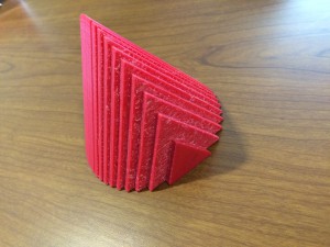
We decided to rotated the area between \(y=x\) and \(y=x^2\) about the line \(y=1.25\). This created a bowl-like object which is curved on the outside, straight on the inside and with a hole at the bottom of the bowl. We split this project up and I created a model of the object using the washer method, while Ryan used the cylindrical shell method. We planned to each use 16 slices/shells so we could compare our two models later.
Creating this object was a very similar process to that of creating the sphere with washers. Since I was using 16 washers and the object has a height of 1, each washer was 1/16 thick. In Cinema4D I used the preprogramed tube object and made each of them to have a height of 1/16. In order to calculate the inner and outer radius of each washer I used the value of middle of each washer, 1/32, 3/32, 5/32, 7/32, etc. I plugged these values into the equation \(f(x)=1.25-x\) for the inner radius value and \(g(x)=1.24-x^2\) for the outer radius value. The only other thing I had to change for each was was its height coordinate. My washers in Cinema4D were parallel to the \(xz\)-plane so I adjusted each washer’s \(y\)-coordinate so they would be spread out to the correct height. I increased the \(y\)-coordinate of each was by 1/16 (the height of each washer) from the previous.
Since I used the preprogramed tube object I was unable to use Magic Merge easily to connect these object and instead just used the ‘Connect + Delete’ command under the ‘Mesh’ tab. This means that there are inner walls in my object, but since each washer is relatively small this is not hugely problematic and adds extra support.
I ran into one issue when I was finishing up with my object. The smallest washer (and the last one I created) did not touch the previous washer.  All the other washers had been able to lie on top of the previous one since their outer radius was larger than the inner radius of the previous washer. The 15th washer had an inner radius of 0.34375 cm and the 16th washer had an outer radius of 0.31152cm and thus there was a gap. This is due to the fact the bowl is very flat at the bottom.
We decided to remedy this we would just delete the 16th washer and make a note of it here as well as in the description of the object on Thingiverse.
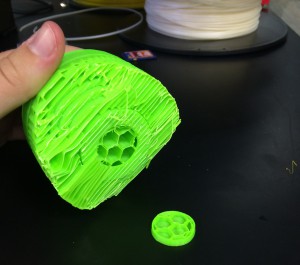
We printed Ryan’s object with cylindrical shells using the Makerbot and the supports on the inside were difficult to remove and didn’t look good. We are currently discussing printing on another printer for these objects and I will update later on how that goes!
 When I went to print my object upright I ran into some problems. It seemed that I had forgotten to merge part of the object and it was printing the inner walls upright which resulted in double the print time and cost. I rotated the object so that the slices were parallel to the build bed – this meant the print required supports. It now looked correct in print preview and printed correctly. My final object from this print looked good, but was rough on one side from removing the supports and I knew if I could fix my problems I would be able to print it with a hollow inside and without supports.
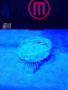 First, the nozzle of the printer became clogged, resulting in a mess of plastic as shown below. We didn’t know what the problem was at this point so we tried twice more only to result in the same mess of plastic filament.

 I decided to make the entire object in Cinema 4D and not use Mathematica at all. In Cinema4D, under the ‘add cube’ button I selected ‘cylinder’ to add cylinders to my working screen. To make these cylinders the correct dimensions for the disk method I used the calculations described above. I also used the same calculations and numbers to find the coordinates of each cylinder in order to line them up to create the sphere. Each cylinder’s coordinates were based on the center of the object so two of the coordinates were 0, while the third was the \(x-\)value described above. (Precisely which of the \(x,y,z\) coordinates were used depended on the orientation I chose for the cylinders).
