Intersecting Cylinders – The Steinmetz Solid

My next goal was to print two cylinders whose axes intersect at right angles and the volume common to both, otherwise known as the Steinmetz solid. I began by modeling these objects in Mathematica so I could import the objects to Cinema 4D as well as create an interactive Mathematica worksheet about these objects.

Here are the Mathematica representations of two objects I planned to print:Screen Shot 2015-06-30 at 3.30.42 PM Screen Shot 2015-06-26 at 1.30.03 PM
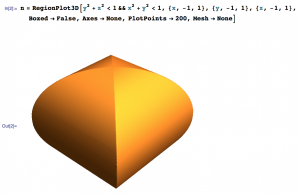
I exported the top object as a .wrl file into Cinema 4D since it was already a solid.

For the bottom object,  I decided it would easiest to create it from scratch in Cinema 4D using the “Tube” object and simply adjusting the dimensions and orientation.

I attempted to print the intersecting cylinders on the Afinia printer in the Math Department. It failed to finish printing because the filament got tangled coming off of the spool. However this was not a complete fail since it shows the inside of the two cylinders and can still be used as a teaching tool. 

I am currently attempting to reprint it and will see how it goes! 

Update: The filament got tangled once again while I was printing resulting in a similar object to the one above. We decided that these were both better teaching tools than the original design and decided not to try to print again. 

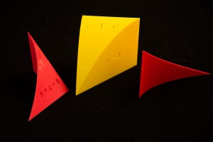
I printed the Steinmetz solid on the MakerBot 2x and had great results! This object can be found on Thingiverse here and here.


An unexpected bonus

Quadratic_Surfaces We have made some wonderful 3d printed models recently. As an unexpected bonus we have also created some great Mathematica notebooks. These were developed as we first created the shapes in Mathematica, then imported them into Cinema 4D, to finally create the .stl file ready for 3d printing. The notebooks have a mix views of the shapes and also some neat Mathematica Demonstrations that can be used when teaching. They can be found here.

Volumes_TripleIntegrals     Two_intersecting_cylinders


Exercise 32

Next, I made a model of the volume from Exercise 32 in Section 12.5 of Stewart’s Essential Calculus. This solid is the region of integration enclosed by the surfaces \(x=0, y=0, y=1-x\), and \(z=1-x^2\).

32_3      32_2

This model is my best by far because the edges are almost perfectly smooth, and each face is very flat. It took about three hours to print, and the only deformities are a little bubble near one edge and the red outline around “\(z=0\)” from of the residual red filament in the extruder. I exported the piece from Mathematica into Cinema 4D, then imprinted the equations into their respective faces (see http://home.wlu.edu/~dennee/math_vis.html for further detail). For this solid I used 300 PlotPoints instead of 100 (see Mathematica code below) and it paid off in the smooth definition of the curved edge, which is almost perfect.

32_1

You can find this object on Thingiverse here.

DSC_1140       DSC_1136

Wedge 2

                                   new_wedge_1

We made some changes before re-printing the wedge enclosed by the surfaces \(x=0, z=0, z=1-y\), and \(x=y^2\). I altered the PlotPoints in the Mathematica code from 100 to 400, which made the curve of intersection between the \(x=y^2\) and \(y+z=1\) surfaces smoother on Cinema 4D.  I also made each side about 8 cm long instead of 7 cm and I made the equations larger.

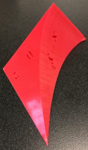
The result was that the top vertex still looks messy and the  “\(z\)” on the bottom face of the object is not clear, but that can be fixed with a razorblade (see image below). Changing the PlotPoints in the Mathematica code made the curve much smoother and the equations look nicer. You can find this object on Thingiverse here.

new_wedge_4              new_wedge_3           


Wedge 1

DSC_1148 Next, I made a model of the volume from Exercise 31 in Section 12.5 of Stewart’s Essential Calculus, which is a wedge with a parabolic cylinder cut out of it.  The wedge is enclosed by the surfaces \(x=0, z=0, z=1-y\), and \(x=y^2\). First I made the solid in Mathematica from the following code (from Professor Keller and Professor Denne):

mathematica_code_1Then I exported it into Cinema 4D by typing the following:

export_code_mathematica


Then I opened the resultant .wrl file in Cinema 4D. The \(x=0\) is tangential to the curved face, so it would not print unless you cut about a half centimeter off of the tangential surface near the \(z\)-axis (I used a Boolean with the solid and a cube to do this). Additionally, I made equations in Adobe Illustrator (I used Times New Roman 36 Bold Italic font). I then extruded them in Cinema 4D to create 3-dimensional letters, and then imprinted them into the four faces of the object. For further instructions, visit http://home.wlu.edu/~dennee/math_vis.html.

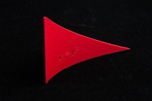
The model looked reasonably good after being printed. The bottom face came out nicely. Near the \(z\)-axis, the solid curled up. Also, the upper edge of the \(x=y^2\) face was a bit jagged, but that can be fixed by changing the Mathematica code (increasing the number of PlotPoints). Additionally, the top vertex of the solid is quite messy, which could be fixed by printing the figure on the slanted face (\(y+z=1\)). Also, Professor Finch suggested that the object could be made a bit larger. A description of improvements to the design and what happened in the second print follows soon. You can find the updated solid on Thingiverse here.

DSC_1136