Torus knots on tori

A white donut shaped surface with a groove on the surface following a smooth curve

The T(3,2) torus knot shown on the torus.

My summer research student Kyle Patterson was interested in printing torus knots together with the tori that they lie on. Recall that torus knots are knots (and links) that can be moved so that they are embedded on a torus (or doughnut shape surface). Kyle constructed torus knots and links using the techniques described in this earlier blog post and this post too.

grey closed curved tube against a black background

T(3,2) torus knot with out the torus.

If we focus our attention on the T(3,2) torus knot, then this knot winds 3 times along the long way and 2 times along the short way around the torus. This knot has the following parametrization: \[ x(t)=\cos(3t)(3+\cos(2t)), \ y(t)= \sin(3t)(3+\cos(2t)), \ z(t) = \sin(2t)\] for t in [0,2π]. We note that the torus this knot lies on is defined by two circles.  We take a large/ring circle of radius 3 (given by equations x2+y2=9, z=0). We make each point of the ring circle the center of a small/pipe circle of radius 1 so that the plane of the pipe circle is perpendicular to the plane of the ring circle.  To construct this torus in Cinema 4D, simply add the Torus shape, then go to the Attributes menu and set the Ring Radius to 3cm and the Pipe Radius to 1cm. In order to have a smooth looking torus we need to change the number of Ring Segments to 150 and the number of Pipe Segments to 50.

grey donut shape with a groove cut into it along a curve against a black background

The torus minus the T(3,2) torus knot.

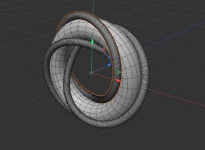
To finish the construction we used the Boole tool in two different ways. First, we took the union of the knot and the torus to create a new surface which reveals the knot lying on the torus. Second, we took the difference of the torus and the knot. This created a torus surface with a smooth groove in the surface following the path of the knot.

We now have three different kinds of files that can be printed. We could print the knot, the torus with the knot, and a torus with a smooth groove following the knot.  We printed the torus with the smooth groove following the T(3,2) torus knot. We also created a 3D print where the knot is one color and the torus is a different color. To do this we use the torus with groove file and the knot file and the Ultimaker5 3D printer in the IQ center at WLU.

We repeated this construction for the T(2,3), T(3,3) and T(3,6) torus knots and links.

White doughnut shape with a red smooth curve on the surface against a brown background

A red T(3,2) torus knot on a white torus.


Torus knots on hyperboloids (part 2)

In the post Hyperboloidal Representation of Torus Knots we gave an explicit construction of T(p,q) torus knots and links where the knots are polygonal and the edges lie on two distinct hyperboloids of one sheet. As the knot is traversed, the edges alternate between lying on the first then the second hyperboloid. Each hyperboloid of one sheet is a doubly ruled surface (as described in the post Doubly ruled surfaces). For each of the hyperboloids the edges of the torus knot lie in one of the rulings.

White curved cylinder shaped surface with line segments on the surface against a brown background

The T(3,5) torus knot lying on two hyperboloids of one sheet.

I wanted to be able to create a 3D-printable model that showed both the T(p,q) knot and the two hyperboloids of one sheet. I used Cinema 4D to do this, and ended up making several attempts to get things just right.

The T(3,5) torus knot was constructed as described in the post Hyperboloidal Representation of Torus Knots. To sum up, the vertices were computed, then the knot was constructed in the standard way.  There are two relatively easy ways to construct the two hyperboloids of one sheet. In the computation for the vertices, we can find an explicit formula for the hyperboloids. We could parametrize a generating hyperbola curve for the hyperboloid, put it into the Formula tool, then use a Lathe tool to rotate the curve around the y-axis. (Remember that in Cinema 4D, the y-axis points up.)
Grey curved cylinder shaped surface on a black background.

The edges of the T(3,5) torus knot lie on these two hyperboloids of one sheet.

Rather than do this, I kept things simple. I added an Empty Spline, opened the Structure Manager, then added in the first three vertices of the T(3,5) torus knot. This created the first two edges of the knot. However, these had the wrong orientation – the vertices were entered for the standard xyz-orientation, not the orientation in Cinema 4D. I thus went into Model mode, and rotated the vertices 90o in the y-direction. I then added a Lathe and moved the Spline under the Lathe. (The reason why this works can be found in the post Doubly ruled surfaces – the formulas explicitly show that you can take one line segment in a ruling and rotate it around the z-axis to create the surface.) At this point the surface had many obvious edges. I went back into the Spline and edited the Object Properties: the Type is Linear, the Intermediate Points is Uniform, the Number is 50. (For some reason Bezier gives a bad looking surface.) I went back into the Lathe and edited the Object Properties. Here I increased the Subdivision to 50.

One of the errors I first made when constructing this surface was to take the coordinates of the vertices of the T(3,5) knot from the 3D printable model. This was a mistake, as the original vertices had been replaced by two nearby vertices for the Chamfer at the corners. This meant the two hyperboloids of one sheet where not correct.

A grey curved cylindrical surface with line segments on it with a black background

The T(3,5) knot on the two hyperboloids of one sheet.

At this point, we can put the object in a better form for 3D printing. One of the adjustments I made was to scale the hyperboloid surface up slightly. When 3D printed, the top and bottom edges of this surface end up each print as one single filament. This can be problematic to print. So increasing the size of the surface slightly gives a bit of wiggle room.  I used the Boole tool (A union B)  to join the hyperboloid surface to the knot. In order to even see the union of these two surfaces, I needed to turn off High Quality in the Object Properties of the Boole. I also created one object from the Boole by going to the Object menu of Objects and then “Current State to Object”. On the new Boole that was created, I selected  “Connect objects + Delete”. I’m not sure these last two steps are entirely necessary. I’ve noticed that the slicing programs for 3D printers are increasingly sophisticated and are able to handle objects that aren’t completely correctly triangulated much more easily than in the past.

Grey curved cylindrical surface with grooves the surface following straight line pattern. Background is black.

The hyperboloid surface without the T(3,5) torus knot.

Finally, I wanted to be able to 3D print the knot in one color and the surface in a different color. I went back into Cinema 4D and created several files. The first was the knot, the second was the surface without the knot. I created this using the Boole tool and the “A subtract B” option. I then printed the surface and the knot on an Ultimaker 5 printer. I had trouble printing this surface as the printer added in unnecessary supports. This is a work in progress! I’ll post an update with a correctly printed knot when we make it happen.


Hyperboloidal Representation of Torus Knots

Written by Timi Patterson (2024 Summer Research Scholar), added to by Elizabeth Denne.

A polygonall (3,5) torus knot arranged on a hyperboloid of one sheet

A T(3,5) torus knot arranged on two hyperboloids of one sheet.

In his book Knots and Links, Peter Cromwell details a representation of torus knots embedded in a parameterization on the union of two hyperboloids. He provides these instructions in Section 1.5:

Choose an angle θ in [0, π/2] and construct two points: \[ A=(\cos\theta, -\sin\theta, -1), \ \ B=(\cos\theta, \sin\theta, 1).\] The straight line through A and B is defined by \[x=\cos\theta, y=z\sin\theta.\] Rotating this line about the z-axis gives the hyperboloid \[x^2+y^2-z^2\sin^2\theta = \cos^2\theta.\] Let Ht denote the annulus obtained by restricting z between the interval from -1 to 1. The boundary curves of the annulus are unit circles: \[ x^2+y^2=1, \ \ z=\pm 1.\] Take the union of two of these Ht annuli with different values of t=theta. This new surface is topologically a torus.

The (p,q) torus knot with p strictly greater than q (and q greater than or equal 2) can be embedded in one of these “hyperboloidal” tori as follows. Choose t=theta and s=phi such that \[ \frac{q}{p}\cdot \frac{\pi}{2} <\theta < \min\{ \frac{\pi}{2}, \frac{q}{p} \pi\} \ \ \ \text{and} \ \ \ \phi = \frac{q}{p}\pi -\theta  .\]  The knot will lie in the torus which is the union of Ht and Hs.

Now take i in {0, 1, 2, … , 2p}. If i is odd, the vertices of the knot are \[ v_i=( \cos((i-1)\pi\frac{q}{p} + 2\theta), \sin((i-1)\pi\frac{q}{p}+2\theta), 1), \] and if i is even, the vertices of the knot are \[v_i =  (\cos((i\pi\frac{q}{p}), \sin(i\pi\frac{q}{p}), -1) .\]

Black and white image of a knot made of 6 edges.

Polygonal (3,2) torus knot whose edges lie on hyperboloids of one sheet.

Following these instructions for the trefoil knot viewed as a T(3,2) torus knot, with\[ \theta = \frac{2\pi}{5} \ \ \text{and} \ \  \phi = \frac{4\pi}{15},\]

I constructed the following vertices:
x y z
1 -0.8090169944 0.5877852523 1.0
2 -0.5 -0.8660254038 -1.0
3 0.9135454576 0.4067366431 1.0
4 -0.5 0.8660254038 -1.0
5 -0.1045284633 -0.9945218954 1.0
6 1.0 0.0 -1.0
Black and white photo of a 4 stick unknot

One component of the T(4,2) torus link.

I first constructed the T(5,3) torus knot in Cinema 4D, as the vertices were detailed in the book. I did this by creating splines using the vertices created by the functions, and using Cinema 4D’s sweep function to create a model with a thickness. I used the Chamfer tool to smooth out the corners. I then went on to create the trefoil knot, the T(10,8) torus knot, the T(4,2), T(12,3), and T(10,8) torus links all in Cinema 4D with the same technique.

Black and white image of 8 line segments, some connected.

The T(4,2) torus link. Note the two components differ by a 90 degree rotation.

To create the links, I had to separate the functions into the different components. Take for example the T(4,2) torus link. When evaluating the formulas, the q/p reduces to 1/2. To then create the two different components of T(2,1), the first component uses the vertices constructed as described above. To construct the vertices of the second component, simply add π/2 to the inside of the trig function in each component. (For example cos(iπ/2 +π/2) for the first term in the even index vertex.) Therefore, I had two components with these vertices (for theta=3π/8 and phi=π/8).

Component 1:

x y z
1 -0.7071067812 0.7071067812 1.0
2 -1.0 0.0 -1.0
3 0.7071067812 -0.7071067812 1.0
4 1.0 0.0 -1.0

Component 2:

x y z
1 0.7071067812 0.7071067812 1.0
2 0.0 -1.0 -1.0
3 -0.7071067812 -0.7071067812 1.0
4 0.0 1.0 -1.0
black and white image of a large number of intersecting line segments

One version of the T(10,8) torus link.

A black and white image of a series of nested interleaved line segments.

A different version of the T(10,8) torus link.

One thing that I experimented with some when working with the T(10,8) torus link is manipulating the theta value to try and reduce any intersections of the model. I created two different models, one with theta=5π/11, the other with theta=5π/12. They varied a lot with where the self-intersections of the tubes were, but alas both of the tubes did self intersect. That will most likely happen with a lot of torus knots or links with p’s and q’s of closer value, but some self-intersections may be able to be avoided by manipulating the theta value,

White knot on brown background

The T(10,3) torus knot.

White link on brown background

The T(10,8) torus link.

I then went on to print out most of these 3D models. The T(10,3) torus knot and T(10,8) torus link are shown above. It turned turns out that these models are surprisingly difficult to print. Take a look at the models. There is only a small area on the base of each V shape. The edges of the knots have to “grow” from this small base. This means the models are unstable. So even though the angle of the edges is high with respect to the ground, the models still need support. We printed several without supports and had some spectacular failures, as shown below. After the edges of the knots fell over on the print bed, the printer kept going leaving a squiggly mess of filament.  The solution to this problem was to increase the angle for the supports from 43 to 55 degrees.

two distinct white spiky shapes on black platforms

Several of the builds failed as the edges of the knots fell over during 3D printing.


New Torus Link, Improved Visualizations, and Cinema 4D Problems.

Written by Hillis Burns, Shannon Timoney, Hall Pritchard (students in Math 383D Knot Theory Spring 2023).

We created the T(2, 8) torus link (or 821 link) using Cinema 4D. The equations for this two component link are x = Cos[t]*(3+Cos[4t]), y = Sin[t]*(3+Cos[4t]), and z = Sin[4t]. The second component is created by the equations x = Cos[t]*(3+Cos[4t+Pi]), y = Sin[t]*(3+Cos[4t+Pi]), and z = Sin[4t+Pi].

We also created the T(3, 3) torus link (or 632 link). With the  632 link, each of the three components goes around the longitude once and goes around the meridian once. The equations for this knot are x1 = Cos[t]*(3+Cos[t]), y1 = Sin[t]*(3+Cos[t]), z1 = Sin[t], x2 = Cos[t]*(3+Cos[t+2*Pi/3]), y2 = Sin[t]*(3+Cos[t+2*Pi/3]), z2 = Sin[t+2*Pi/3], and x3 = Cos[t]*(3+Cos[t+4*Pi/3]), y3 = Sin[t]*(3+Cos[t+4*Pi/3]), z3 = Sin[t+4*Pi/3].

Image showing the T(3,3) torus link lying on the torus.

The T(3,3) torus link shown lying on the torus.

After creating the T(3, 3) or 632 link, we wanted to build a model that helps demonstrate what the torus link actually is. We did this by first opening back up the T(3, 6) or 632  in Cinema 4D. Then we created a torus surface and rotated it 90° so that the torus link sat in the right position on the torus surface. Then we changed the radius of both the meridian and the longitude so that the 3d model was in a presentable format. Our final model which is shown above gives a good physical representation of how a torus link is constructed.

We also created the  T(3, 6) torus link (or 633 link). With the 633 link, each of the three components goes once around the longitude and goes three times around the meridian. The equations for this knot are x1 = Cos[t]*(3+Cos[2t]), y1 = Sin[1t]*(3+Cos[2t]), z1 = Sin[2t], x2 = Cos[t]*(3+Cos[2t+2*Pi/3]), y2 = Sin[t]*(3+Cos[2t+Pi]), z2 = Sin[2t+2*Pi/3], and x3 = Cos[t]*(3+Cos[2t+4*Pi/3]), y3 = Sin[t]*(3+Cos[2t+4*Pi/3]), z3 = Sin[2t+4*Pi/3].

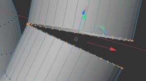
While using the Cinema 4D software, the biggest problem we had was fixing the join at the end of two strands. In Cinema 4D, the join will sometimes not look correct. In order to fix this, we will first decrease the period of the parametric equations in order to make the join fully noticeable. We decreased it from 2π (~6.28) to 6.275.

Image showing the two ends of the torus link with too many points highlighted

Too many points are highlighted near the ends of the torus link.

We then try to highlight all the points at the end of the knot, in order to use the “stitch and sew” function. We came across problems when we accidentally highlighted other points not at the end. This is shown in the figure to the right. This would happen more often when we increased the sample size to a number that was higher than necessary (>300). This is the case in the image below. By decreasing the sample size, it made it easier to highlight just the end points of the knot, as shown below. At this point we were able to successfully use the “stitch and sew” function.

Image showing points highlighted along the ends of the torus link.

This image shows that just the end points of the two ends of the torus link are highlighted. This allowed us to successfully use the Stitch and Sew function to join the ends together.

Overview of Torus Shapes, Knots, and Links

Written by Hillis Burns, Shannon Timoney, Hall Pritchard (students in Math 383D Knot Theory Spring 2023).

Image of a torus with a 3 component link on it

The T(3,6) torus link.

The torus is the surface of a donut in 3-dimensions. A torus knot/link is a knot/link that can be moved to lay on the torus surface in R3.The image on the right shows a link being wrapped to lie on a torus; this is the T(3, 6) or 633 torus link. Knots are also commonly described in knot tables using the notation, Crnj. The crossing number is denoted by Cr, the number of components by n, and the certain configuration is j. As seen in this image, the torus has two key circles: the longitude, which wraps around the long way of the torus, and the meridian, which wraps around the short way. These are illustrated in the image below.

Image of a torus showing the longitude and meridian curves

A torus with some Longitude and Meridian curves highlighted.

The notation for torus knots is T(p, q); The knot wraps around the longitude p times, while it wraps q times around the meridian. The two figures are from a Mathematica file which visualizes torus links, and this website. This Knot Plot website also has a neat table showing many of the torus knots and links.

Using a Mathematica file provided by Professor Denne, we were able to start creating the T(2, 4) torus link (or 421) in Cinema 4D. This is a two-component link where each component goes once around the longitude and twice around the meridian, as illustrated below.

Image showing the T(2,4) torus link

The T(2,4) torus link.

The parametric equations that create the link are x =  Cos[t]*(2+Cos[2t]), y = Sin[t]*(2+Cos[2t]), z = Sin[2t], with t going from 0 to 2Pi. However, for this link there are two components. Thus, a second equation was needed for the second component. To create a torus link like this, the second equation must be rotated 180 degrees to fit with the first curve. To do that, we added Pi to the trigonometric equations of the first sweep: x = Cos[t]*(3+Cos[2t+Pi]),  y = Sin[t]*(3+Cos[2t+Pi]), z = Sin[2t+Pi].

We also decided to create the T(2, 11) torus knot (also known as 111) in addition to the links in Cinema 4D. This is a knot (one component link) where the curve goes twice around the longitude and 11 times around the meridian. The topmost figure below shows the original image of the torus knot that we created. The knot does not look smooth, as Cinema 4D only evaluated a few points along the parametrized curve. However, after adding more sample points we were able to make the torus knot smoother. The progression of sample points, from 20, to 50, to 100, to 200, is shown from top to bottom:

T(2,11) with 20 sample pointsT(2,11) with 50 sample points

T(2,11) with 100 sample pointsT(2,11) with 200 sample pointsWe also had to adjust the radius because the loops were too close together. In order to spread out the components, the radius was changed from 2 to 3.

Next, we created a T(2, 6) torus link (or 621) in Cinema 4D. With the 621, each of the two components goes once around the longitude and three times around the meridian. Using the Mathematica file, we knew that the equations for this link were, x = Cos[t]*(3+Cos[3t]),  y = Sin[t]*(3+Cos[3t]),  z = Sin[3t].  The second component’s equations, again rotated by Pi, consist of, x = Cos[t]*(3+Cos[3t+Pi]), y = Sin[t]*(3+Cos[3t+Pi]),  z = Sin[3t+Pi].