In the last post, I described how I designed a 3D printable Schwarz P surface unit for the Taping Shape* exhibit at the Rueben H. Fleet Science Center. In the process of designing that surface, I made two other approximations of the Schwarz P surface. These did not end up in the exhibit, but making them was interesting.
When I was first looking at the Schwarz P surfaces, I found some great graphics on the web here.  I downloaded the .wrl file from there, then edited it in Cinema4D to get one Schwarz P cubical unit. It turns out that this apparently smooth model has an interesting triangulation. (You can select commands in a 3D modeling program to smooth out the edges when it is rendered.) I’m not exactly sure how the folks designed their surface, it is less smooth than my model, but is possibly more mathematically accurate.
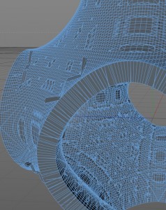
As before, I extruded the surface by 5mm and added caps. I found I needed to clean up the rims of the surface, they weren’t level. To do this, I went into Point Mode, then selected the points along the rim. I then used the Set Point Value command (Mesh → Commands → Set Point Value) to set the appropriate \(x\), \(y\), or \(z\) coordinates to be the same. After that, I adjusted some points by hand, and fixed some overlapping polygons near the rim. (By deleting a vertex or polygon as needed, then using the Close Polygon and Knife tools to fill in and tidy up the shape.) I then added in magnet holes as before. I made both a 6cmx6cmx6cm and 10cmx10cmx10cm size model. The figure above shows a comparison between my mostly smooth model and this version. You can find the files for the model, and instructions on how to place the magnets here on Thingiverse.
It turns out that the Schwarz P surface may be approximated by the level surface \(\cos(x)+\cos(y)+\cos(z)=0\). I created this surface in Mathematica, then downloaded it as a .wrl file. I then imported that into Cinema4D. The surface had a very complex triangulation. After playing around for a bit, I worked out that the best thing to do was to optimize the surface once, then extrude the surface 5mm with caps.
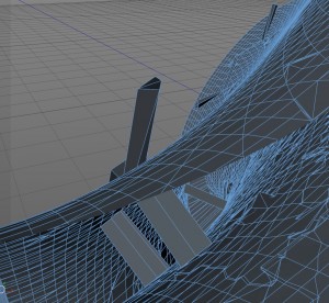
Unfortunately, the surface needed a lot of editing!  As seen on the left, parts of the surface extended outwards and needed removing. I went into Point Mode and simply deleted these pieces. Worse, there were parts of surfaces inside the model as shown below on the left. Many 3D printers won’t print objects with pieces inside like this. I removed these surfaces, by going into Polygon Mode and deleting them. Alas, tiny holes sometimes appeared in the surface afterwards, and needed to be filled. There were also many overlapping or missing triangles as shown below on the right. I ended up going over the entire surface (inside and out) and fixing these problems. Some printers would have been able to ignore these triangles, others would not. Fixing these surfaces was a labor of love, but worth it in the end.
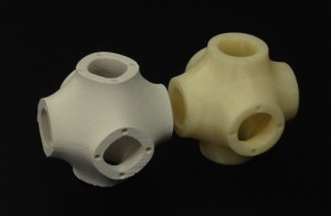
Once all the editing was complete, I added in magnet holes as before. I made both a 6cmx6cmx6cm and 10cmx10cmx10cm size model. I printed these on both the MakerBot 2X and uPrint SE printers, the 6cm size is shown below. You can find the files for the model, and instructions on how to place the magnets, here on Thingiverse.
*The Taping Shape exhibit is part of the InforMath project funded by the National Science Foundation (DRL-1323587). (The InforMath Project is a partnership between San Diego State University and several museums at the Balboa Park, including the Rueben H. Fleet Science Center .)


