
My second project this summer was to create a solid with a circular base and with equilateral triangles as the parallel cross-sections perpendicular to the base. I modeled this solid with 20 triangles and 10 triangles.
In order to create the triangular prism cross-sections I used Mathematica. I decided to use the circle \(x^2+y^2=25\) for my base, and assumed that the cross-sections were perpendicular to the \(y\)-axis. In Mathematica, the triangular prisms were created using coordinates for the three vertices and the desired thickness. For the 20-slice object each triangle prism was 0.5 cm thick and for the 10-slice object they were 1 cm. I calculated the three coordinates for each cross-section by using the midpoint of each slice. So for the 20-slice object I used \(y\)-values of 0.25, 0.75, 1.25, 1.75, 2.25, 2.75, 3.25, 4.25, and 4.75. (I only had to use 10 values since due to the symmetry of the circle.) Similarly, for the 10-slice object I used \(y\)-values of 0.5, 1.5, 2.5, 3.5 and 4.5. I then calculated the \(x\)-formula for the points on the circle using \(x=\sqrt{25-y^2}\). The three coordinates of the triangle were then \((-x,y), (x,y) \), and \((0,x\sqrt{3})\). To make it easier to create the triangular prisms in Mathematica, I shifted the bottom left corner to each triangle to the origin so that the three coordinates for my equilateral triangles were \((0,0), (2x, 0) \), and \( (x, x\sqrt{3}) \). After creating each slice I exported the triangular prisms from Mathematica as .wrl files and imported them into Cinema 4D.
In Cinema 4D I arranged each slice to have the correct coordinates and created my objects. Since these slices were created in Mathematica I could extend them from only one side and not both (like with the disks in my previous post). This was perfect for using the plugin Magic Merge. I wanted to extend the triangles from one side into the larger one next to them in order to use Magic Merge. This is where I ran into trouble! Each triangle would only extend from one side and, since the smaller triangles had to overlap with larger ones in order to maintain the mathematical accuracy from my calculations, that meant half of them wouldn’t overlap.
In order to fix this, I had to rotate those individual triangles 180° and changed their coordinates accordingly so that I would be able to extend them correctly to overlap. Once I had done this I used Magic Merge to create the solid and then exported the .stl file for printing.
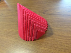 When I went to print my object upright I ran into some problems. It seemed that I had forgotten to merge part of the object and it was printing the inner walls upright which resulted in double the print time and cost. I rotated the object so that the slices were parallel to the build bed – this meant the print required supports. It now looked correct in print preview and printed correctly. My final object from this print looked good, but was rough on one side from removing the supports and I knew if I could fix my problems I would be able to print it with a hollow inside and without supports.
I went back and merged all of my cross sections again (and this is another reason to always save a separate file of your object before you merge because this makes things a lot easier to check). Now when I exported the file and went to print, my print preview only had certain parts of the object showing up. When I tried to fix this I realized that I hadn’t checked the normals of the slices I had imported from Mathematica. Going back to my saved file I changed the normals so they all aligned in the correct direction. Now I could finally print my object upright with a hollow inside thanks to Magic Merge. These objects can be found on Thingiverse here and here.
